PART 1
Alright first things first this is on my 2003 GMC 2500HD Sierra SLT 4x4 with a 6” Trailmaster lift. As far as I know this process should be the same and work for most all 2500 and 3500 series trucks to at least 2005 with factory stock steering, as far as wrench and socket sizes go they should be the same also because I still have all stock GM steering components. I did not include pictures of the pitman arm or the Idler arm and pivot as these are pretty self explanatory even for a first timer. So without further a-due, here we go.
Idler Arm Replacement: (on right or passenger side of vehicle) You will need a Pitman arm puller (about 15 bucks to buy one or rent it for free from your local parts place). First remove any front skid plate, remove nut from the stud in center link, use puller to remove arm stud from center link, remove the (2) bolts from the idler arm pivot, now remove idler arm and pivot together from vehicle. Replace with Moog K6723 Idler arm pivot and K6535 idler arm. Install arm to pivot then install to frame and tighten bolts to (73 ft lb), install rubber seal to ball stud and install stud in center link and tighten new nut to (46 ft lb).
Pitman Arm Replacement: (on left or driver side of vehicle) You will need a 1 5/16” box end wrench and puller noted from above. First remove 1 5/16” nut and washer from steering gear spline, remove nut from the stud in center link, use puller to remove arm stud from center link, then use puller to remove pitman arm from steering gear and remove from vehicle. (Tip: before placing puller on arm, slide the rubber boot on the steering gear spline up into the steering box as you do not want to damage this boot. Next Tip: remove original bolt from the puller and replace it with a 5/8x18x2 grade 8 bolt. Now screw the new bolt into the puller from the opposite side you took the original bolt out from, this should allow the puller to clear the frame cross member beneath the steering box. Next Tip: if the arm does not want to come off the steering gear spline, break out the dremel with cutting wheel and cut a slot in it, but not so deep as to cut into the steering gear spline, then take a chisel and hammer to break it the rest of the way through) Replace with Moog K6654 pitman arm. Install arm to steering gear then install rubber seal to ball stud and install stud in center link and tighten new nut to (46 ft lb), now reinstall steering nut and washer and tighten to (184 ft lb). (Tip: since you won’t get a torque wrench in above the frame cross member just tighten it to real “f”ing tight) Now slide rubber boot back down over steering gear spline, reinstall any front skid plate and done.
Now the real fun begins.
This process will take you through stripping the whole front wheel side to the bare control arms to replace tie rods, wheel hub and seal, upper and lower control arm ball joints. I did not replace the CV drive axels but six more bolts per side and that could have been done too. You will need to set aside a full day to do this or 3 to 4 hours a side on average. I have done several of these and can do a full side in about 2 hours start to finish. Just be patient take your time and don’t sweat it.
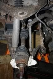
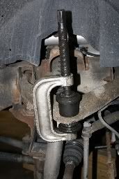
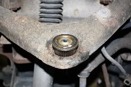
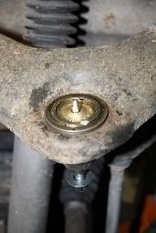
Pick a side to start on then raise and support the vehicle on heavy jack stands, remove tire and wheel. You should now see something like (Figure 1). Use an 18mm socket to relieve tension on the torsion bar, loosening bolt until almost flush with top of the bolt keeper in frame (Figure 2) making sure to count and record each full turn. (Tip: it is much easier to loosen any and all nuts and bolts now while everything is still hooked together)
![Image]()
Figure 1
![Image]()
Figure 2
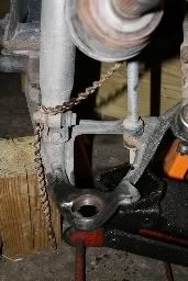
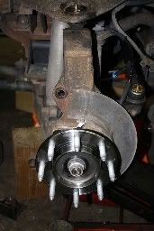
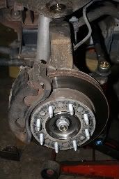
Removing Brake Caliper and Rotor: Insert a large screwdriver through the brake caliper into one of the rotor vanes in order to prevent the rotor from turning. (Figure 3) First use a large C-clamp to press the caliper pistons back into the bores or just use a large screwdriver to pry open the brake pads wide enough to slide off the rotor. Now take a 36mm axel nut socket (Figure 3) and loosen the axel nut and washer. Loosen the (2) 18mm caliper bolts, loosen the (2) 21mm caliper bracket bolts, loosen the (4) 15mm wheel hub bolts (Figure 4). Now remove brake caliper and tie off to swaybar out of the way (Figure 5), remove caliper bracket, remove rotor, un-plug wheel speed sensor, (little blue plug on top of shock tower in Figure 6) and you should now see something similar to (Figure 7).
![Image]()
Figure 3
![Image]()
Figure 4
![Image]()
Figure 5
![Image]()
Figure 6
![Image]()
Figure 7
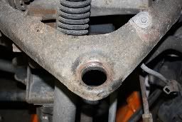
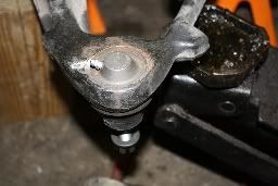
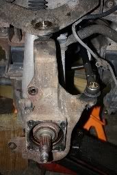
Removing Wheel Hub: Remove axel nut and washer, remove the (4) hub bolts and pull hub from axel, (Tip: if the hub does not easily pull from the axel, a few light taps with a hammer should loosen it, if not use a large three arm puller to remove it) remove dust shield and you should now see something similar to (Figure 8).
![Image]()
Figure 8
Alright first things first this is on my 2003 GMC 2500HD Sierra SLT 4x4 with a 6” Trailmaster lift. As far as I know this process should be the same and work for most all 2500 and 3500 series trucks to at least 2005 with factory stock steering, as far as wrench and socket sizes go they should be the same also because I still have all stock GM steering components. I did not include pictures of the pitman arm or the Idler arm and pivot as these are pretty self explanatory even for a first timer. So without further a-due, here we go.
Idler Arm Replacement: (on right or passenger side of vehicle) You will need a Pitman arm puller (about 15 bucks to buy one or rent it for free from your local parts place). First remove any front skid plate, remove nut from the stud in center link, use puller to remove arm stud from center link, remove the (2) bolts from the idler arm pivot, now remove idler arm and pivot together from vehicle. Replace with Moog K6723 Idler arm pivot and K6535 idler arm. Install arm to pivot then install to frame and tighten bolts to (73 ft lb), install rubber seal to ball stud and install stud in center link and tighten new nut to (46 ft lb).
Pitman Arm Replacement: (on left or driver side of vehicle) You will need a 1 5/16” box end wrench and puller noted from above. First remove 1 5/16” nut and washer from steering gear spline, remove nut from the stud in center link, use puller to remove arm stud from center link, then use puller to remove pitman arm from steering gear and remove from vehicle. (Tip: before placing puller on arm, slide the rubber boot on the steering gear spline up into the steering box as you do not want to damage this boot. Next Tip: remove original bolt from the puller and replace it with a 5/8x18x2 grade 8 bolt. Now screw the new bolt into the puller from the opposite side you took the original bolt out from, this should allow the puller to clear the frame cross member beneath the steering box. Next Tip: if the arm does not want to come off the steering gear spline, break out the dremel with cutting wheel and cut a slot in it, but not so deep as to cut into the steering gear spline, then take a chisel and hammer to break it the rest of the way through) Replace with Moog K6654 pitman arm. Install arm to steering gear then install rubber seal to ball stud and install stud in center link and tighten new nut to (46 ft lb), now reinstall steering nut and washer and tighten to (184 ft lb). (Tip: since you won’t get a torque wrench in above the frame cross member just tighten it to real “f”ing tight) Now slide rubber boot back down over steering gear spline, reinstall any front skid plate and done.
Now the real fun begins.
This process will take you through stripping the whole front wheel side to the bare control arms to replace tie rods, wheel hub and seal, upper and lower control arm ball joints. I did not replace the CV drive axels but six more bolts per side and that could have been done too. You will need to set aside a full day to do this or 3 to 4 hours a side on average. I have done several of these and can do a full side in about 2 hours start to finish. Just be patient take your time and don’t sweat it.
Pick a side to start on then raise and support the vehicle on heavy jack stands, remove tire and wheel. You should now see something like (Figure 1). Use an 18mm socket to relieve tension on the torsion bar, loosening bolt until almost flush with top of the bolt keeper in frame (Figure 2) making sure to count and record each full turn. (Tip: it is much easier to loosen any and all nuts and bolts now while everything is still hooked together)
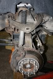
Figure 1
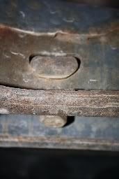
Figure 2
Removing Brake Caliper and Rotor: Insert a large screwdriver through the brake caliper into one of the rotor vanes in order to prevent the rotor from turning. (Figure 3) First use a large C-clamp to press the caliper pistons back into the bores or just use a large screwdriver to pry open the brake pads wide enough to slide off the rotor. Now take a 36mm axel nut socket (Figure 3) and loosen the axel nut and washer. Loosen the (2) 18mm caliper bolts, loosen the (2) 21mm caliper bracket bolts, loosen the (4) 15mm wheel hub bolts (Figure 4). Now remove brake caliper and tie off to swaybar out of the way (Figure 5), remove caliper bracket, remove rotor, un-plug wheel speed sensor, (little blue plug on top of shock tower in Figure 6) and you should now see something similar to (Figure 7).
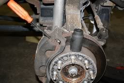
Figure 3
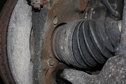
Figure 4
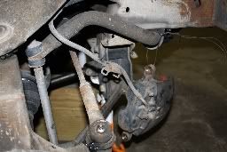
Figure 5
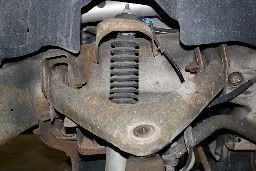
Figure 6
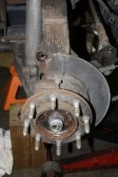
Figure 7
Removing Wheel Hub: Remove axel nut and washer, remove the (4) hub bolts and pull hub from axel, (Tip: if the hub does not easily pull from the axel, a few light taps with a hammer should loosen it, if not use a large three arm puller to remove it) remove dust shield and you should now see something similar to (Figure 8).
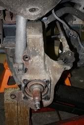
Figure 8
")