Document ID: 5258414
DTC P149F, P208A-P208D, P214E, or P2C11
Diagnostic Instructions
DTC DescriptorDTC P149F
Reductant Pump Resistance Performance
DTC P208A
Reductant Pump Control Circuit
DTC P208B
Reductant Pump Performance
DTC P208C
Reductant Pump Control Circuit Low Voltage
DTC P208D
Reductant Pump Control Circuit High Voltage
DTC P214E
Reductant Pump High Current
DTC P2C11
Reductant Pump Low Current
Diagnostic Fault Information
Circuit | Short to Ground | Open/High Resistance | Short to Voltage | Signal Performance |
|---|
Control A | P208C | P208A | P208D | — |
Control B | P208C | P208A | P208D | — |
Control C | P208C | P208A | P208D | — |
Low Reference | — | — | — | — |
Circuit/System Description
For an overview of the component/system, refer to:
Exhaust Aftertreatment System Description
Circuit | Description |
|---|
Control | The output circuit varies between ground and 12 V. The motor is bidirectional. |
Low Reference | Grounded through the control module. |
Conditions for Running the DTCP208A, P208C, P208D, P214E
- DTC P10F4, P20FF, U010E = Not set
- Ignition = On or Engine = Running
- Ignition Voltage = Greater than 11 V
Frequency the DTC runs = Continuously — After the running conditions are met
P149F, P208B, P2C11
- DTC P10C9, P10CA, P10DA, P10DB, P14FA, P20FF, U010E, U2412, U2626 = Not set
- DTCs related to the following system/component = Not Set B194 Reductant Pressure Sensor
- No other DTCs related to the concerned component are set.
- Ignition = On or Engine = Running
- Ignition Voltage = Greater than 11 V
Frequency the DTC runs = Continuously — After the running conditions are met — For greater than 63 s
Conditions for Setting the DTC
P149F
Reductant Pump = Resistance Out Of Range
P208A
Control Circuit = Open
P208B
Reductant Pump Speed = Not within a calibrated range
P208C
Control Circuit = Short to Ground
P208D
Control Circuit = Short to Voltage
P214E
Control Circuit = High Current
P2C11
Control Circuit = Low Current
Actions Taken When the DTC Sets
DTCs listed in the DTC Descriptor category = Type A DTC
Warning Message = Service Emission System / Service Exhaust Fluid System
Conditions for Clearing the DTC
DTCs listed in the DTC Descriptor category = Type A DTC
Reference InformationSchematic Reference
Engine Controls Schematics
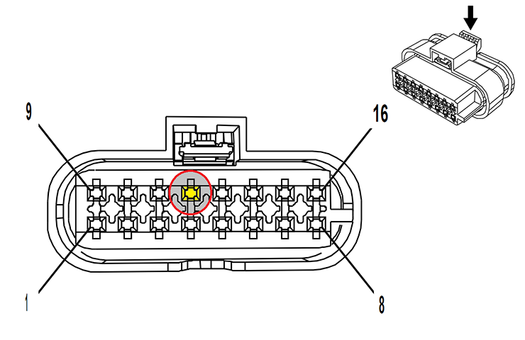
Connector End View Reference
Master Electrical Component List
Electrical Information Reference
DTC Type Reference
Powertrain Diagnostic Trouble Code (DTC) Type Definitions
Scan Tool Reference
Control Module References
Circuit/System Verification
- Ignition » On / Vehicle » In Service Mode
- Verify DTC P10C9, P10CA, P10DA, P10DB, P14FA ,P204B, P204C, P204D, P204E, P20FF, U010E, U2412, U2626 is not set.
- Operate the vehicle within the Conditions for Running the DTC. You may also operate the vehicle within the conditions that you observed from the Freeze Frame/Failure Records data.
Verify the DTC does not set.
- If the DTC sets
Refer to: Circuit/System Testing
- If the DTC does not set
- All OK.
Circuit/System Testing
- Note: It may take up to 2 min for all vehicle systems to power down before an accurate ground or low reference circuit continuity test can be performed.
- Ignition/Vehicle & All vehicle systems » Off
- Disconnect the electrical connector: A38 Reductant Pump and Sensor Assembly
- Test for less than 10 Ω between the test points: Low Reference circuit terminal 14 & Ground
- Disconnect the electrical connector: @ K115 Reductant Control Module
- Test for less than 2 Ω between the test points: Low Reference circuit terminal 14 @ Component harness & Terminal 36 @ Control module harness
- If 2 Ω or greater » Repair the open/high resistance in the circuit.
- If less than 2 Ω » Replace the component: K115 Reductant Control Module
- Disconnect the electrical connector: @ K115 Reductant Control Module
- Test for less than 2 Ω between the test points:
- Control circuit terminal 7 @ Component harness & Terminal 37 @ Control module harness
- Control circuit terminal 8 @ Component harness & Terminal 24 @ Control module harness
- Control circuit terminal 16 @ Component harness & Terminal 11 @ Control module harness
- If greater than 2 Ω
Repair the open/high resistance in the circuit:
- If less than 2 Ω
- Test for infinite resistance between the test points:
- Control circuit terminal 7 @ Component harness & Ground
- Control circuit terminal 8 @ Component harness & Ground
- Control circuit terminal 16 @ Component harness & Ground
- If less than infinite resistance
Repair short to ground on the circuit.
- If infinite resistance
- Ignition » On / Vehicle » In Service Mode
- Test for less than 1 V between the test points:
- Control circuit terminal 7 @ Component harness & Ground
- Control circuit terminal 8 @ Component harness & Ground
- Control circuit terminal 16 @ Component harness & Ground
- If greater than 1 V
Repair the short to voltage on the circuit:
- If less than 1 V
- Replace the component: A38 Reductant Pump and Sensor Assembly
- Operate the vehicle within the Conditions for Running the DTC. You may also operate the vehicle within the conditions that you observed from the Freeze Frame/Failure Records data.
Verify the DTC does not set.
- If the DTC sets
Replace the component: K115 Reductant Control Module
- If the DTC is not set
- All OK.
Repair Instructions
Perform the Diagnostic Repair Verification after completing the repair:
Diagnostic Repair Verification
Additional Procedures
Note: Performing this procedure will clear the Driver Information message for the applicable system.
Perform the scan tool control function:
Reductant System Tamper Warning Service Bay Test — Perform only when the following warning message is displayed: Service Emission System / Service Exhaust Fluid System