Chevy and GMC Duramax Diesel Forum banner

L5P Battery Wiring

2 reading
28K views 62 replies 8 participants last post by  Dmax060717  
#1 ·
Does anyone have a wiring diagram for the 2018 Duramax passenger-side battery or is able to tell me where each of the connections I have labelled in the image terminate? I have looked everywhere but my Google-fu is weak! I am connecting a Mechman 400 second alternator as well as running 2/0 wire to the rear cab for a 5kw inverter. Appreciate any help!
 

Attachments

#2 ·
I don't have the answer but I can tell you the batteries and alternator(s) are in parallel with no isolation devices or anything between them, so you can connect your aftermarket alternator directly to the existing alternator or either battery without any problems.

But you're going to need a lot bigger wire than 2/0 to pull 5kw from an inverter mounted in the rear of the cab.

Image


A voltage drop of 1.6V at 400A means over 640w of resistive heat to be dissipated. If the run is 40 feet round trip that means you're somewhere around 15-20 watts per linear foot of cable. That's way too much; they're going to get hot. And 20 feet is pretty conservative for one-way distance, to be honest. 25 is probably more realistic. So you may encounter voltage drop issues that will create problems for your inverter even aside from the heat dissipation problem.

I put a 3kw inverter in my truck (see link in my sig) and I used 4/0. For 5kw you probably need 2x 4/0 or 400 MCM. If you go with 2x 4/0 you will need to fuse both runs separately and ensure the lengths are almost identical, and finding space for two ANL fuse blocks and busbars is not going to be easy. If you go with 400 MCM the size of the lugs may be prohibitive and make it difficult to impossible to connect to the existing electrical system.

Personally, I think more than a single strand of 4/0 is just going to be too cumbersome. If I were you I'd run 4/0 and fuse it at 300A which will give you almost 4kw.

Cool project regardless. Good luck!
 
#5 ·
Thanks for the info! Every calculator and amperage chart I have used shows me the same thing you get. My run is 12' each way so 24' with a return ground. Mechman said all I need is 1/0 as does custombatterycables.com, although they suggested going up to 2/0 to be safe.
 
#3 ·
#1 driver side battery
#2 under hood fuse box
#3 alternator
#4 glow plug module
#5 starter
#6 ground going to the engine block
#7 ground going to fron cab mount behind tire.
 
  • Like
Reactions: 1Blue78
#7 ·
Honestly I’m not sure what would go there. It might be used in the gas trucks I believe with some other spots empty. Dual alternator factory attaches to the drivers side battery.
 
#13 ·
I just got off the phone with DirectWire who suggested several products that meet a 400A @ 13VDC rating @125C. According to their ampacity chart, which they say is based on the NEC rating scale, we can do 410A using 3/0 wire. DIRECT-Type-SGX-Cross-Linked-Spec-Sheet-R11-20-v2.pdf (directwire.com) I also measured the run and it is a maximum of 12' each way. So it appears my voltage drop would be 0.49/3.76%. If I go up to 4/0 then my voltage drop is 2.98.
 
#18 ·
X50D Fuse Block - Battery Top View (except HP5)


Usage Table
No.Device Label NameDevice Assigned NameRatingDescription
Fuses


F1UD 1


F1UD —


F1UD F1UD


F1UD 100A


  • F1UD E40 Electrical Auxiliary Heater (L5P)

F2UD 2


F2UD —


F2UD F2UD


F2UD 175A


  • F2UD X50A Fuse Block - Underhood


  • F2UD G13 Generator

F3UD 3


F3UD —


F3UD F3UD


F3UD 125A


  • F3UD KR79 Auxiliary Battery Relay 2 (K4D)


  • F3UD K34 Glow Plug Control Module (L5P)

F4UD 4


F4UD —


F4UD F4UD


F4UD 175A


  • F4UD K43 Power Steering Control Module (1500)

F7UD 9


F7UD —


F7UD F7UD


F7UD 60A


  • F7UD X51R Fuse Block - Instrument Panel Right

F8UD 10


F8UD —


F8UD F8UD


F8UD 60A


  • F8UD X51R Fuse Block - Instrument Panel Right
 
#19 ·
After talking to several cable manufacturers and running a 12.5' test line to confirm the distance from the battery to the inverter, I am going to use 4/0 SGX pure copper cable and run both the positive and negative cables directly from the battery. Does anyone have any suggestions as to the best way to connect the 4/0 lugs to the battery terminals? I had hoped to be able to do it without cutting the OEM cabling already run to the posts.
 
#20 ·
Good call on the 4/0. Read the thread in my signature; I show how to connect everything. You should connect the lugs to the alternator(s) rather than the batteries.
 
#22 ·
Thanks man. One thing I will say I wish I had done differently is how I got the cables into the cab. If I had to do it over I would use a separate waterproof cable gland for each cable (there are four in my case).

I'd also read the posts starting here because I had a problem with the original fuse block that basically caused a meltdown. You really need to make sure that the cable is physically supported in the vicinity of any lug connections, for which lock washers are a must.

Let me know if you have any other questions. I have used my inverter a lot and in a variety of applications.
 
#26 ·
After two trips to NAPA to get the right serpentine belt, I just completed the install of the 400A Mechman in the 2008 GMC Sierra 3500HD Duramax. Fortunately I was replacing the radiator hoses at the same time so I had a lot more room to install the new belt. Now that I have it physically installed, I am working on the wiring. Unlike my 2018 Chevy, which is next, there is plenty of room in the 2008 to fuse the two alternators together then route the 4/0 cables to the back. Since my second alternator is an aftermarket install, it is not connected to the battery on the driver side. From your photos, it looks like your OEM install has a cable going from the second alternator to the driver side battery. Is this the case and, if so, should I run one to it as well and what size cable?
 
#28 ·
So this is somewhat speculative, but just hear me out.

When you're pulling lots of power off your inverter while the truck is idling, your amperage draw will exceed the capacity of the alternator at idle. But that's okay, because the over-drawing causes voltage drop, and the ECM reacts by increasing the idle speed to get the voltage back up.

But, if the hot side of the alternator powering the inverter is connected only to the inverter (i.e., it's isolated from the rest of the truck, including the ECM), then the ECM will not be able to detect that the voltage is dropping and hence won't increase the RPMs to compensate. This will likely result in the inverter's low-voltage cutoff being exceeded, and the inverter will shut down.

Again, that's rather speculative, but the fact that all my stuff is bonded together and works perfectly leads me to advise that you do it the same way.

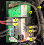
As for the wire size to the battery, I would probably just use the same gauge that is used on the OEM alternator, which I suspect is 2 AWG. But I would use 4/0 for the alternator-alternator bond, if you choose to do one like I did. I recommend doing this because if you don't, then some of the current to the inverter will be pulled from the other alternator, and you don't want big amperage going through those 2 AWG battery cables.

Also, you ran your ground cable to the second alternator. Any issues with running it from the grounding lug on the engine block instead? The passenger side battery is ground to the engine block near the bottom of the engine and there is a straight shot from the bolt to the frame rail running to the back seat, so it would save about 4 feet of cable.
I went straight to the alternator housing because I wanted as few cable/lug interfaces (including the physical connection between the alternator and the block and any intermediate brackets) in the circuit. I think going to the block is probably fine though.
 
#27 ·
Also, you ran your ground cable to the second alternator. Any issues with running it from the grounding lug on the engine block instead? The passenger side battery is ground to the engine block near the bottom of the engine and there is a straight shot from the bolt to the frame rail running to the back seat, so it would save about 4 feet of cable.
 
#33 ·
JD, we opted to outfit our 2022 Ram 2500 with your cabling design before we do the duallies. It came with 2 x 220A alternators. We fused the two alternators with 4/0 SGX battery cable and what a PITA! The posts are on the bottom of the alternators! Regardless, with a lot of swearing and torn up forearms, we got that done then ran the cable to the 400A T-fuse block, then 12 feet to the passenger compartment where the 5000W inverter resides. Here is where we ran into problems. Since there is no room in the engine compartment, we first tried grounding through the frame. This lead to a voltage drop from 14.2VDC to 10.6VDC under a 33amp AC load at 1500RPM high-idle. Ouch! Next we connected the frame to the starter motor mounting bolt with 4/0 cable, which got us to 11.8VDC under a 37 amp AC load. Tomorrow we are going to connect from the starter-to-frame bolt back to the inverter-to-frame bolt, which should give us 4/0 copper all the way to the engine block as per your instructions! LOL It should also give us the frame as a return along with copper. Quick question, in your setup, what is your voltage drop under max load? Under the 37 amp AC load, we measured 450 amps on the DC side going into the inverter and the alternators were running strong. The truck, with everything on consumes 50 amps, so I would say the alternators are producing more than rated.
 
#34 ·
Sounds like it's coming together. When I tested the voltage drop I used two 1500w electric space heaters, which at 13.5 VDC should be somewhere on the order of 220A. I think I recall the voltage drop being about 0.5 VDC, and according to a voltage drop calculator it should be 0.56 VDC for a 20-ft run (my cables are much longer than yours), so I think that's about what it was.

Oh and let's see some pics!
 
#39 ·
Looks okay to me. How did you connect the terminals to the wire? I used a 16-ton hydraulic crimper.

Is the bolt you're using for ground the same connection the starter uses for ground? You need to make sure it's not just a structural bolt for securing the starter because in that case it could have very weak continuity to ground. I'd try to go directly to the alternator if possible. Doesn't matter which because they're both bolted directly to the block and by necessity the alternator housings have to have good continuity to the block.

On a side note, I can't tell from the pics but have you ensured that the wire is sufficiently separated from the exhaust manifold? You don't want your wire anywhere near that thing.
 
#58 ·
@ScottC any updates? If you have time it would be great if you could post a thread with pictures and some guidance for folks undertaking such a project. We get a lot of questions about inverters here and right now my thread is the only real resource.