I didn't see too much detailed information on installing a large inverter in one of these trucks, so I rolled the dice and just went about it the best way I could determine. I think it turned out reasonably well. It's not the cleanest install imaginable, but it's easily removed for vehicle trade-in or sale purposes. Note that I did this install late last year, and have since driven over 5,000 miles with absolutely zero electrical issues, so I think it's a sound installation.
I chose the AIMS 3kw inverter-charger because AIMS is a well-reputed manufacturer of this sort of equipment, and I wanted the charging capability because I am considering building a large power pack for my camper, and I wanted to get familiar with how these things function. Better to spend an additional $300 now then blow it on a $3,000 inverter later. However, for most vehicle inverter applications, the charging isn't really necessary unless you want to be able to run your vehicle's accessories off AC.
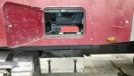
I also wanted auxiliary outlets in the truck bed, so I made sure I chose an inverter with hardwire terminals. In retrospect, I should have put the outlets and inlet closer to the tailgate so they could be accessed easily without climbing into the bed. I could move them, but I'd have to either run new wire to the inverter or install a junction box somewhere to make the connection because the existing wire isn't long enough.
The bed outlets are a standard 20A GFCI outlet and a NEMA L5-30R. I chose the latter to make this installation mirror what you'd find on a 3kw generator. For my RV I have an L5-30 > TT-30 adapter, and a TT-30 > 14-50 adapter, so I can connect my 50-amp plug to the inverter via the bed outlet and utilize the full 3kw (the draw on the 20A outlets should not exceed 2.4 kw). You could just as easily use a TT-30 outlet, though, if your only application is an RV.
Now, for the numbers. My truck has dual alternators, 220A and 150A, for a combined maximum output of 370A. I also had the high-idle software added to my truck by the dealer so I can raise the idle speed to about 1200RPM via the cruise control button, which would be a good idea if a large continuous load is to be placed on the charging system at idle. 370A * 12V = 4.4kw, so 3kw should be well within the system's capabilities, although I admit to being unfamiliar with the magnitude of thermal losses due to the DC/AC conversion. 3kw / 12V = 250A, so I needed cable/terminals/fuses that could handle this huge current. The 4/0 welding cable is actually right around its limit at that amperage, but it's readily available (as are terminals, fuses, etc.) so I decided it was the best solution. 3kw/120V = 25A, so I went with 10-gauge SOOW (flexible) cable for the AC connection to the auxiliary outlets and inlet. This cable can handle about 30 amps for non-continuous loads or 24 amps for a continuous load (80% of intermittent load capacity), which is close enough to the theoretical maximum 25A that I can draw from the inverter continuously. More cautious types could go with 8-gauge.
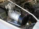
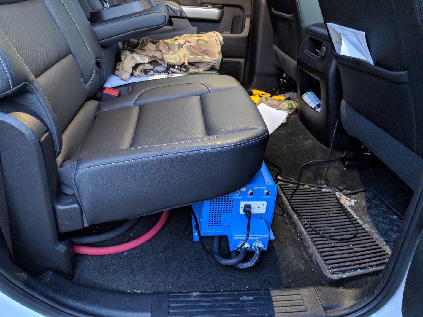
I thought long and hard about where to locate the inverter. Putting it in the bed would totally eliminate the issue of routing cables into the cab, but the inverter would then be exposed to the elements without constructing some elaborate (and space-consuming) enclosure. I decided to play it safe and located it under the rear passenger-side seat. The particular inverter I chose is very tall, and I was just barely able to install it such that it does not interfere with the seat or the foot room in front of it. It is not the most aesthetically pleasing location but hey, it's a truck. Also, this inverter's ventilation holes are on its sides, so I don't think the fact that the top of it is covered is a problem. I knew I would have to drill a hole somewhere, and I wanted it to be easily concealable, so I did it in the back of the cab below the rear seat. I used a hole saw and installed a 2-1/4" clamp connector to protect the cables; note that the one I linked to above is only 2" (can't seem to find the 2-1/4" on Home Depot's website). It was extremely difficult routing the cables through the connector; if I were to do it again, I would go with two smaller holes and clamps. I was able to screw the clamp down on the cables enough that I didn't feel like I had to use any sealant, but I guess you could use silicone or something to totally eliminate the air gap.
Some of you may be wondering about the dedicated neutral wire. For the amount of current that this system needs to be able to handle, I did not want to roll the dice on the resistance across all the body/frame/engine/alternator connections, especially since many of these connections are exposed to the elements and may be subject to increasing resistance through time due to corrosion, dirt, rock salt, etc. The other thing that may be odd-looking is the bond I installed between the two alternators' positive terminals. I did a continuity test from one alternator to the other with the truck in its original configuration and found that there's no resistance between the two (it's one continuous system), but I realized that the current path from one alternator to the other routes through small (relatively speaking) 2-gauge cables to each battery and then to the starter. So if I made the connection to only one alternator, the current path from the other alternator to the inverter connection would be alternator 2 > battery > starter > battery > alternator 1, all through those smaller cables which have no overcurrent protection and could become very hot if I were drawing a full 3kw from the inverter. Plus, the voltage drop could make the system unable to provide the full 3kw at all. Therefore, I bonded them together with a small length of the welding cable.
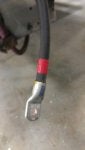
Aside from the hole I had to drill in the cab, the only really annoying part of the installation was routing the huge cables out of the engine bay. I had to remove the passenger-side battery to install the fuse block anyway, so while I was in there I pushed the cables through a small gap between the sheet metal that constitutes the fender. I then removed the wheel well shroud from outside (it's held in by little Torx screws) and was able to route the cables on the inside of this shroud down to the back of the passenger side front wheel well and have them pop out right next to the frame rail. From there I routed them over the running board anchors and secured them with zip-ties. I covered the exposed positive cable with wire loom as an extra added protection against the possibility of the insulation being compromised from road debris or some unforeseeable catastrophe. To secure the inverter to the floor I just used two 2-1/2" self-tapping hex-head screws from Home Depot and drilled right through the carpet and into the metal floor below (after checking under the cab about a dozen times to make sure I wasn't going to hit anything).
The install works about as well as I could have hoped. I am able to run a pair of 1500-watt space heaters off it simultaneously. I don't even have to use the high idle; as soon as the truck's electrical system detects the voltage drop (at that load, the alternators can't supply the needed current at idle so the batteries begin to deplete) it increases the RPM on its own. One thing I have not yet tested is starting my 15k BTU/hr air conditioner, which is an important test because the space heaters are resistive (as opposed to inductive, like the AC's compressor) loads and, as such, their starting current is no higher than their running current. Update: the inverter has no problem starting and running my 15k BTU/hr air conditioner, even while simultaneously powering my 1200-watt water heater, DC power converter, and refrigerator.
I may have forgotten some details, so if you have any questions feel free to ask. Rather than answer in a reply, however, I'll probably just add the relevant information to this initial post so that anyone reading this in the future will be able to find all of the info in one place.
Edit 1: A note on circuit breakers and fuses. I tried a 300A circuit breaker and it tripped under a load that I estimate to be about 230A. At that point I decided to go the simpler route of a fuse and block, and just deal with replacing the fuse in the (extremely unlikely) event that I ever blow one. Breakers can degrade over time, and my understanding is that they're designed to "fail safe," so they'll trip at lower, rather than higher currents than their rated capacity. I don't have detailed or technical knowledge of circuit breakers, so it would be interesting to hear others' experiences in this area.
Edit 2: For reference, the length of my cables (neutral and hot) is about 20 feet, for a total length of 40 feet from the hot side of the alternator to the inverter and back to the neutral side. Less is always better, as wire has finite resistance. Remember, P = (I^2)*R (where P=power [watts], I=current [amps], and R=resistance [ohms]). This means that your power loss due to a given resistance is going to be much greater if that resistance is on the 12 VDC side as opposed to the 120 VAC side. How much greater? Well, for a given value of P and R, the current on the 12 VDC side (upstream of the inverter) will be 10 times greater than the current on the 120 VAC side (downstream of the inverter). 10^2 == 100, therefore the heat (or power) dissipated across the same value of R (assuming a corresponding impedance on the 120 VAC side) will be one hundred times greater. Coupling this with the understanding that the cable or wire used to transmit the power has its own resistivity (resistance per unit length), it's easy to see why you're always better off locating the inverter as close to the DC voltage source as possible in order to minimize the length of cable that the low-voltage DC current has to flow through. You can always just use extension cords or hardwire some auxiliary outlets on the 120 VAC side. This is a much better solution than locating the inverter far away from the alternator(s).
Edit 3: If you are going to install something like this, I recommend doing a "bench test," in which you wire up your inverter with the correct-length cables, fuse block and/or breaker and anything else and load it under your worst-case scenario conditions, but before actually drilling any holes or routing cables. A poster below proposed the use of bulkhead connections instead of drilling a large hole in the cab; if you do this, make sure those bulkhead connections are used in your bench test, as those connections have finite resistance. Also, do not use bulkhead connections for any 120 VAC circuits! Doing so poses a major electrocution hazard.
Edit 3A: There is a discussion about the safety of using bulkhead conductors for 120 VAC somewhere between posts 10 and 20 of this thread. I maintain my recommendation -- in the strongest possible terms -- against doing this, but if you have a strong fundamental understanding of electromagnetism you may be capable of doing the requisite analysis to safely deviate from standard practices and implement this design.
Edit 3B: I've done some more thinking about the use of bulkhead conductors for 120 VAC circuits. I still think it's a bad idea, but it's not necessarily suicidal/homicidal provided that you are using GFCI for all your circuits and the inverter's ground terminal on the AC side is bonded to the vehicle chassis. This gets a lot more complicated if you are using an inverter-charger that may be connected to shore power, because you need to make sure that your inverter has an internal relay that breaks the chassis-neutral bonding when shore power is supplied. If it doesn't, then an open neutral connection on the shore power side could result in the vehicle chassis being energized at line voltage. In that scenario, if the inverter circuit is not GFCI-protected, you're basically asking for someone to be electrocuted. If what you just read doesn't make perfect sense, just drill the damn holes for your 120 VAC cables and insulation.")
Edit 4: A note on AC cable/wire selection. You could use Romex for the auxiliary connections, but solid-core cabling like Romex needs to be secured such that it's never really subjected to any kind of physical movement. The one advantage (aside from cost) to using Romex is that it's easy to connect to hardwire terminals. What I wound up doing was using outdoor-rated flexible SOOW cable, and then inside the auxiliary outlet and power inlet gangboxes I connected the SOOW to the outlets/inlets using a very short (three inches or so) length of 10/2 Romex and wire nuts. I did this because the stranded SOOW cable is difficult to insert into the hardwire terminals on the outlets/inlets. The gangboxes got pretty crowded, though. You could skip this and tie the SOOW in directly, but you need to be extremely careful about individual strands of the wire not seating fully and remaining exposed, as this nearly guarantees a ground fault (electrocution hazard!) or short circuit.
Edit 5: You will need serious cable cutters to cut 4/0 effectively and without creating a mess. The cutters I link to below will work, but something larger would probably be better. For stripping insulation I just used a sharp box cutter and was very careful not to cut any of the strands.
Edit 6: Here is a handy voltage drop calculator. My parameters are:
Wire Material: Copper
Wire Size: 4/0 AWG
Voltage: 14 (approximate alternator voltage)
Phase: DC
Number of conductors: single set of conductors
Distance: 20 feet (it specifies one-way distance, not round-trip)
Load Current: 250A
I get a voltage drop of 0.49V, which sounds about right as compared to my practical measurements. You can measure voltage drop at a specific inverter load by measuring V_alternator - V_inverter. V_alternator is the voltage measured across the alternator's positive terminal and its metal housing. V_inverter is the voltage measured across the inverter's positive and negative terminals. Both measurements need to be taken while the inverter is under load; i.e., the values will be different for different loads. Do this during your bench test. If your voltage drop is significantly greater than what the calculator predicts, take a look at your connections and any other resistive devices in the current path (fuse/block, bulkhead conductors, etc.) and see how bypassing them affects the drop. Of course, you can't bypass the fuse/block for the full install, but if you find that it's adding significant resistance you will realize ahead of time that there's some debris or other issue that needs to be addressed before you go any further; these issues are much easier to diagnose with all the wiring and other hardware exposed than post-install. Remember, if V_inverter drops below some specified cutoff voltage (probably 10.5 V), the inverter will shut itself off. And don't forget that resistance under load means heat dissipation, at a rate of I^2*R.
Below are links to some of the hardware I used for the install:
AIMS 3kw inverter-charger: https://www.amazon.com/gp/product/B00NZCRFRQ/ref=oh_aui_detailpage_o02_s01?ie=UTF8&psc=1
16-ton hydraulic crimper (the 10-ton is not large enough for the terminals I used): https://www.amazon.com/gp/product/B00GXQ2E5E/ref=oh_aui_detailpage_o01_s00?ie=UTF8&psc=1
ANL fuse block: https://www.amazon.com/gp/product/B000K2K7TW/ref=oh_aui_search_detailpage?ie=UTF8&psc=1
300A ANL fuses: https://www.ebay.com/itm/300A-AMP-A...ted-High-Quality-Fuses-6-Pack-Car-Audio-Blade-/173191129908?hash=item2852feeb34
4/0 terminals: https://www.amazon.com/gp/product/B00030CYU6/ref=oh_aui_detailpage_o02_s00?ie=UTF8&psc=1
4/0 flexible welding cable (black): https://www.amazon.com/gp/product/B00KD27670/ref=oh_aui_detailpage_o02_s00?ie=UTF8&psc=1
4/0 flexible welding cable (red): https://www.amazon.com/Gauge-Premiu...F3T2BK5B12QHTF0Z&pd_rd_w=CI1XU&pd_rd_wg=igc4s&psc=1&refRID=EBQAF3T2BK5B12QHTF0Z
Heat shrink (red): https://www.amazon.com/gp/product/B01F2LG3JS/ref=oh_aui_detailpage_o00_s00?ie=UTF8&psc=1
Heat shrink (black): https://www.amazon.com/gp/product/B01F2LGF5U/ref=oh_aui_detailpage_o00_s00?ie=UTF8&psc=1
3/4" wire loom (red): https://www.amazon.com/gp/product/B00TE1SCQU/ref=oh_aui_detailpage_o06_s01?ie=UTF8&psc=1
10/3 SOOW cord: https://www.homedepot.com/p/Southwi...oot-10-3-600-Volt-CU-Black-Flexible-Portable-Power-SOOW-Cord-55809799/204632922
15-amp power inlet (outdoor rated): https://www.gordonelectricsupply.co...BRBMEiwAmKSB8yYhMgcbfabQHNAQbLEU_3qj2oGwrS3G3vLhgB7sYfZ0Zmsd5hn4CRoCJMkQAvD_BwE
2-inch clamp connector (EXAMPLE -- see discussion above): https://www.homedepot.com/p/Halex-2...om/p/Halex-2-in-Non-Metallic-NM-Sheathed-Cable-Clamp-Connectors-05120/100127021
Cable cutters: https://www.homedepot.com/p/Pro-sKi...etj85Y1zKRneqqgkiAhkz4-2oOwdZrQNAaAgrvEALw_wcB&dclid=CIHVwZW8gNoCFYS9swodiUcOgQ
![Image]()
![Image]()
![Image]()
![Image]()
![Image]()
![Image]()
![Image]()
![Image]()
![Image]()
![Image]()
![Image]()
![Image]()
![Image]()
![Image]()
![Image]()
![Image]()
![Image]()
![Image]()
Update: The install looks a lot cleaner with these Maxliner floor mats covering the cables routed under the back seat.
![Image]()
![Image]()
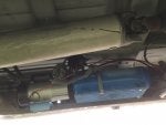
UPDATE: I've since relocated the in-bed inlet/outlet to make room for my auxiliary fuel tank. This has the added benefit of making the inlet/outlet accessible while standing behind the tailgate. I definitely should have done it this way from the outset.
![Image]()
![Image]()
![Image]()
![Image]()
I chose the AIMS 3kw inverter-charger because AIMS is a well-reputed manufacturer of this sort of equipment, and I wanted the charging capability because I am considering building a large power pack for my camper, and I wanted to get familiar with how these things function. Better to spend an additional $300 now then blow it on a $3,000 inverter later. However, for most vehicle inverter applications, the charging isn't really necessary unless you want to be able to run your vehicle's accessories off AC.
I also wanted auxiliary outlets in the truck bed, so I made sure I chose an inverter with hardwire terminals. In retrospect, I should have put the outlets and inlet closer to the tailgate so they could be accessed easily without climbing into the bed. I could move them, but I'd have to either run new wire to the inverter or install a junction box somewhere to make the connection because the existing wire isn't long enough.
The bed outlets are a standard 20A GFCI outlet and a NEMA L5-30R. I chose the latter to make this installation mirror what you'd find on a 3kw generator. For my RV I have an L5-30 > TT-30 adapter, and a TT-30 > 14-50 adapter, so I can connect my 50-amp plug to the inverter via the bed outlet and utilize the full 3kw (the draw on the 20A outlets should not exceed 2.4 kw). You could just as easily use a TT-30 outlet, though, if your only application is an RV.
Now, for the numbers. My truck has dual alternators, 220A and 150A, for a combined maximum output of 370A. I also had the high-idle software added to my truck by the dealer so I can raise the idle speed to about 1200RPM via the cruise control button, which would be a good idea if a large continuous load is to be placed on the charging system at idle. 370A * 12V = 4.4kw, so 3kw should be well within the system's capabilities, although I admit to being unfamiliar with the magnitude of thermal losses due to the DC/AC conversion. 3kw / 12V = 250A, so I needed cable/terminals/fuses that could handle this huge current. The 4/0 welding cable is actually right around its limit at that amperage, but it's readily available (as are terminals, fuses, etc.) so I decided it was the best solution. 3kw/120V = 25A, so I went with 10-gauge SOOW (flexible) cable for the AC connection to the auxiliary outlets and inlet. This cable can handle about 30 amps for non-continuous loads or 24 amps for a continuous load (80% of intermittent load capacity), which is close enough to the theoretical maximum 25A that I can draw from the inverter continuously. More cautious types could go with 8-gauge.
I thought long and hard about where to locate the inverter. Putting it in the bed would totally eliminate the issue of routing cables into the cab, but the inverter would then be exposed to the elements without constructing some elaborate (and space-consuming) enclosure. I decided to play it safe and located it under the rear passenger-side seat. The particular inverter I chose is very tall, and I was just barely able to install it such that it does not interfere with the seat or the foot room in front of it. It is not the most aesthetically pleasing location but hey, it's a truck. Also, this inverter's ventilation holes are on its sides, so I don't think the fact that the top of it is covered is a problem. I knew I would have to drill a hole somewhere, and I wanted it to be easily concealable, so I did it in the back of the cab below the rear seat. I used a hole saw and installed a 2-1/4" clamp connector to protect the cables; note that the one I linked to above is only 2" (can't seem to find the 2-1/4" on Home Depot's website). It was extremely difficult routing the cables through the connector; if I were to do it again, I would go with two smaller holes and clamps. I was able to screw the clamp down on the cables enough that I didn't feel like I had to use any sealant, but I guess you could use silicone or something to totally eliminate the air gap.
Some of you may be wondering about the dedicated neutral wire. For the amount of current that this system needs to be able to handle, I did not want to roll the dice on the resistance across all the body/frame/engine/alternator connections, especially since many of these connections are exposed to the elements and may be subject to increasing resistance through time due to corrosion, dirt, rock salt, etc. The other thing that may be odd-looking is the bond I installed between the two alternators' positive terminals. I did a continuity test from one alternator to the other with the truck in its original configuration and found that there's no resistance between the two (it's one continuous system), but I realized that the current path from one alternator to the other routes through small (relatively speaking) 2-gauge cables to each battery and then to the starter. So if I made the connection to only one alternator, the current path from the other alternator to the inverter connection would be alternator 2 > battery > starter > battery > alternator 1, all through those smaller cables which have no overcurrent protection and could become very hot if I were drawing a full 3kw from the inverter. Plus, the voltage drop could make the system unable to provide the full 3kw at all. Therefore, I bonded them together with a small length of the welding cable.
Aside from the hole I had to drill in the cab, the only really annoying part of the installation was routing the huge cables out of the engine bay. I had to remove the passenger-side battery to install the fuse block anyway, so while I was in there I pushed the cables through a small gap between the sheet metal that constitutes the fender. I then removed the wheel well shroud from outside (it's held in by little Torx screws) and was able to route the cables on the inside of this shroud down to the back of the passenger side front wheel well and have them pop out right next to the frame rail. From there I routed them over the running board anchors and secured them with zip-ties. I covered the exposed positive cable with wire loom as an extra added protection against the possibility of the insulation being compromised from road debris or some unforeseeable catastrophe. To secure the inverter to the floor I just used two 2-1/2" self-tapping hex-head screws from Home Depot and drilled right through the carpet and into the metal floor below (after checking under the cab about a dozen times to make sure I wasn't going to hit anything).
The install works about as well as I could have hoped. I am able to run a pair of 1500-watt space heaters off it simultaneously. I don't even have to use the high idle; as soon as the truck's electrical system detects the voltage drop (at that load, the alternators can't supply the needed current at idle so the batteries begin to deplete) it increases the RPM on its own. One thing I have not yet tested is starting my 15k BTU/hr air conditioner, which is an important test because the space heaters are resistive (as opposed to inductive, like the AC's compressor) loads and, as such, their starting current is no higher than their running current. Update: the inverter has no problem starting and running my 15k BTU/hr air conditioner, even while simultaneously powering my 1200-watt water heater, DC power converter, and refrigerator.
I may have forgotten some details, so if you have any questions feel free to ask. Rather than answer in a reply, however, I'll probably just add the relevant information to this initial post so that anyone reading this in the future will be able to find all of the info in one place.
Edit 1: A note on circuit breakers and fuses. I tried a 300A circuit breaker and it tripped under a load that I estimate to be about 230A. At that point I decided to go the simpler route of a fuse and block, and just deal with replacing the fuse in the (extremely unlikely) event that I ever blow one. Breakers can degrade over time, and my understanding is that they're designed to "fail safe," so they'll trip at lower, rather than higher currents than their rated capacity. I don't have detailed or technical knowledge of circuit breakers, so it would be interesting to hear others' experiences in this area.
Edit 2: For reference, the length of my cables (neutral and hot) is about 20 feet, for a total length of 40 feet from the hot side of the alternator to the inverter and back to the neutral side. Less is always better, as wire has finite resistance. Remember, P = (I^2)*R (where P=power [watts], I=current [amps], and R=resistance [ohms]). This means that your power loss due to a given resistance is going to be much greater if that resistance is on the 12 VDC side as opposed to the 120 VAC side. How much greater? Well, for a given value of P and R, the current on the 12 VDC side (upstream of the inverter) will be 10 times greater than the current on the 120 VAC side (downstream of the inverter). 10^2 == 100, therefore the heat (or power) dissipated across the same value of R (assuming a corresponding impedance on the 120 VAC side) will be one hundred times greater. Coupling this with the understanding that the cable or wire used to transmit the power has its own resistivity (resistance per unit length), it's easy to see why you're always better off locating the inverter as close to the DC voltage source as possible in order to minimize the length of cable that the low-voltage DC current has to flow through. You can always just use extension cords or hardwire some auxiliary outlets on the 120 VAC side. This is a much better solution than locating the inverter far away from the alternator(s).
Edit 3: If you are going to install something like this, I recommend doing a "bench test," in which you wire up your inverter with the correct-length cables, fuse block and/or breaker and anything else and load it under your worst-case scenario conditions, but before actually drilling any holes or routing cables. A poster below proposed the use of bulkhead connections instead of drilling a large hole in the cab; if you do this, make sure those bulkhead connections are used in your bench test, as those connections have finite resistance. Also, do not use bulkhead connections for any 120 VAC circuits! Doing so poses a major electrocution hazard.
Edit 3A: There is a discussion about the safety of using bulkhead conductors for 120 VAC somewhere between posts 10 and 20 of this thread. I maintain my recommendation -- in the strongest possible terms -- against doing this, but if you have a strong fundamental understanding of electromagnetism you may be capable of doing the requisite analysis to safely deviate from standard practices and implement this design.
Edit 3B: I've done some more thinking about the use of bulkhead conductors for 120 VAC circuits. I still think it's a bad idea, but it's not necessarily suicidal/homicidal provided that you are using GFCI for all your circuits and the inverter's ground terminal on the AC side is bonded to the vehicle chassis. This gets a lot more complicated if you are using an inverter-charger that may be connected to shore power, because you need to make sure that your inverter has an internal relay that breaks the chassis-neutral bonding when shore power is supplied. If it doesn't, then an open neutral connection on the shore power side could result in the vehicle chassis being energized at line voltage. In that scenario, if the inverter circuit is not GFCI-protected, you're basically asking for someone to be electrocuted. If what you just read doesn't make perfect sense, just drill the damn holes for your 120 VAC cables and insulation.
Edit 4: A note on AC cable/wire selection. You could use Romex for the auxiliary connections, but solid-core cabling like Romex needs to be secured such that it's never really subjected to any kind of physical movement. The one advantage (aside from cost) to using Romex is that it's easy to connect to hardwire terminals. What I wound up doing was using outdoor-rated flexible SOOW cable, and then inside the auxiliary outlet and power inlet gangboxes I connected the SOOW to the outlets/inlets using a very short (three inches or so) length of 10/2 Romex and wire nuts. I did this because the stranded SOOW cable is difficult to insert into the hardwire terminals on the outlets/inlets. The gangboxes got pretty crowded, though. You could skip this and tie the SOOW in directly, but you need to be extremely careful about individual strands of the wire not seating fully and remaining exposed, as this nearly guarantees a ground fault (electrocution hazard!) or short circuit.
Edit 5: You will need serious cable cutters to cut 4/0 effectively and without creating a mess. The cutters I link to below will work, but something larger would probably be better. For stripping insulation I just used a sharp box cutter and was very careful not to cut any of the strands.
Edit 6: Here is a handy voltage drop calculator. My parameters are:
Wire Material: Copper
Wire Size: 4/0 AWG
Voltage: 14 (approximate alternator voltage)
Phase: DC
Number of conductors: single set of conductors
Distance: 20 feet (it specifies one-way distance, not round-trip)
Load Current: 250A
I get a voltage drop of 0.49V, which sounds about right as compared to my practical measurements. You can measure voltage drop at a specific inverter load by measuring V_alternator - V_inverter. V_alternator is the voltage measured across the alternator's positive terminal and its metal housing. V_inverter is the voltage measured across the inverter's positive and negative terminals. Both measurements need to be taken while the inverter is under load; i.e., the values will be different for different loads. Do this during your bench test. If your voltage drop is significantly greater than what the calculator predicts, take a look at your connections and any other resistive devices in the current path (fuse/block, bulkhead conductors, etc.) and see how bypassing them affects the drop. Of course, you can't bypass the fuse/block for the full install, but if you find that it's adding significant resistance you will realize ahead of time that there's some debris or other issue that needs to be addressed before you go any further; these issues are much easier to diagnose with all the wiring and other hardware exposed than post-install. Remember, if V_inverter drops below some specified cutoff voltage (probably 10.5 V), the inverter will shut itself off. And don't forget that resistance under load means heat dissipation, at a rate of I^2*R.
Below are links to some of the hardware I used for the install:
AIMS 3kw inverter-charger: https://www.amazon.com/gp/product/B00NZCRFRQ/ref=oh_aui_detailpage_o02_s01?ie=UTF8&psc=1
16-ton hydraulic crimper (the 10-ton is not large enough for the terminals I used): https://www.amazon.com/gp/product/B00GXQ2E5E/ref=oh_aui_detailpage_o01_s00?ie=UTF8&psc=1
ANL fuse block: https://www.amazon.com/gp/product/B000K2K7TW/ref=oh_aui_search_detailpage?ie=UTF8&psc=1
300A ANL fuses: https://www.ebay.com/itm/300A-AMP-A...ted-High-Quality-Fuses-6-Pack-Car-Audio-Blade-/173191129908?hash=item2852feeb34
4/0 terminals: https://www.amazon.com/gp/product/B00030CYU6/ref=oh_aui_detailpage_o02_s00?ie=UTF8&psc=1
4/0 flexible welding cable (black): https://www.amazon.com/gp/product/B00KD27670/ref=oh_aui_detailpage_o02_s00?ie=UTF8&psc=1
4/0 flexible welding cable (red): https://www.amazon.com/Gauge-Premiu...F3T2BK5B12QHTF0Z&pd_rd_w=CI1XU&pd_rd_wg=igc4s&psc=1&refRID=EBQAF3T2BK5B12QHTF0Z
Heat shrink (red): https://www.amazon.com/gp/product/B01F2LG3JS/ref=oh_aui_detailpage_o00_s00?ie=UTF8&psc=1
Heat shrink (black): https://www.amazon.com/gp/product/B01F2LGF5U/ref=oh_aui_detailpage_o00_s00?ie=UTF8&psc=1
3/4" wire loom (red): https://www.amazon.com/gp/product/B00TE1SCQU/ref=oh_aui_detailpage_o06_s01?ie=UTF8&psc=1
10/3 SOOW cord: https://www.homedepot.com/p/Southwi...oot-10-3-600-Volt-CU-Black-Flexible-Portable-Power-SOOW-Cord-55809799/204632922
15-amp power inlet (outdoor rated): https://www.gordonelectricsupply.co...BRBMEiwAmKSB8yYhMgcbfabQHNAQbLEU_3qj2oGwrS3G3vLhgB7sYfZ0Zmsd5hn4CRoCJMkQAvD_BwE
2-inch clamp connector (EXAMPLE -- see discussion above): https://www.homedepot.com/p/Halex-2...om/p/Halex-2-in-Non-Metallic-NM-Sheathed-Cable-Clamp-Connectors-05120/100127021
Cable cutters: https://www.homedepot.com/p/Pro-sKi...etj85Y1zKRneqqgkiAhkz4-2oOwdZrQNAaAgrvEALw_wcB&dclid=CIHVwZW8gNoCFYS9swodiUcOgQ


Update: The install looks a lot cleaner with these Maxliner floor mats covering the cables routed under the back seat.


UPDATE: I've since relocated the in-bed inlet/outlet to make room for my auxiliary fuel tank. This has the added benefit of making the inlet/outlet accessible while standing behind the tailgate. I definitely should have done it this way from the outset.